Draw Deployment Diagram Online Free
Create a UML deployment diagram
Visio Programme 2 Visio Plan i Visio Professional person 2021 Visio Professional 2019 More than...Less
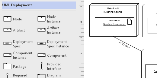
Yous can create a UML Deployment diagram to show the architecture of a deployment of software artifacts to nodes. First, you open the UML Deployment template and pick i of the four template options. And then the UML Deployment stencil appears, along with shapes that arrange to the UML two.v standard.
Start a UML Deployment diagram
-
Start Visio. Or if you have a file open up already, click File > New.
-
Go to Categories > Software and Database > UML Deployment.
-
Select the blank template or 1 of the three starter diagrams. When you've picked the template you desire, click Create.
-
You should see the Shapes window next to the diagram. If you lot don't run into it, get to View > Task Panes and make sure that Shapes is selected. If you nevertheless don't see it, click the Aggrandize the Shapes window push
 on the left.
 -
On the View tab, make sure the check box next to Connexion Points is selected. This will brand connection points appear when y'all start connecting shapes.
-
Now, drag shapes yous want to include in your diagram from the Shapes window to the page. To rename text labels, double-click the labels.
Start a UML Deployment diagram
-
Open up Visio for the spider web. Nigh the upper right, select More templates.
-
In the Gallery, scroll down to the UML Deploymentrow, most midway down the page.
The first item in the row represents a bare template plus the companion stencil. The other items in the row are sample diagrams that take some shapes already drawn to assistance you lot get started chop-chop.
-
Click any item to come across a larger preview.
-
When you find the diagram you want to use, click its Create push button.
The new diagram, with the related stencil, opens in your browser.
Node instances and artifacts
When to apply
-
Utilize Node Case shapes when you desire to specify an case of a run-time computational or concrete device.
-
Put Artifact Instance shapes inside node instance shapes to deploy artifacts.

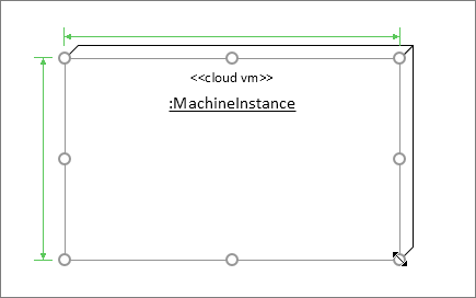
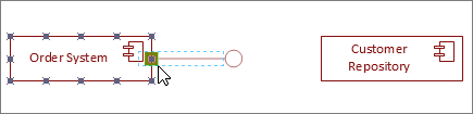
Step one
Drag a Node Instance shape to the folio first, then make it bigger by dragging the shape handles.
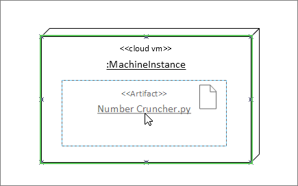
Footstep 2
Elevate an Antiquity Instance shape and place it inside the larger node shape. When you see a green highlight, this means the smaller shape will be contained within the larger node shape. From that betoken forward, when the node shape moves, the artifact within will move every bit well.
Other container shapes
There are other container shapes available in the UML Deployment stencil. They comport like the Node Example shape. That is, when you drop shapes on top of them, the shapes are glued and volition move with the container. Here are some of the most popular container shapes for deployment diagrams:
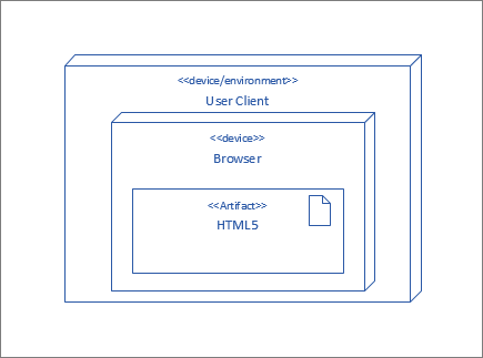
Hierarchical nodes
Nest node shapes inside each other when yous want to testify them hierarchically.
Package shapes
Use Package shapes when you demand to correspond containing elements like a binder.
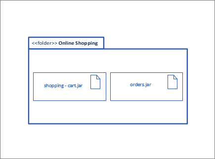
Diagram Overview
Apply the Diagram Overview shape when you want to environs all of the shapes with a frame.

Tips for connectors
Straighten connectors
If a connector is taking too many turns, right-click it, and so click Straight Connector.
Bear witness multiplicity
If needed, correct-click the connector and select Bear witness Multiplicity. When you lot're done, iv text boxes appear where y'all can add details. If yous do non need all the text boxes, delete the ones you don't demand.
Change connector type
You lot tin can change a connector blazon. For example, you tin modify from an Clan to a Directed Association. Correct-click the connector, and then click Set Connector Type.
Brand dynamic connections instead of point connections
If yous anticipate moving shapes a lot, consider making a dynamic connection instead of a betoken connection.
Move or rotate text on connectors
Near likely y'all'll demand to rotate or move text on your connector lines. Here'southward how to exercise that:
-
Click an empty area of the page to deselect anything that may be selected.
-
On the Abode tab, in the Tools group, click the Text Block tool

-
Click the connector that has text your desire to rotate or move.
-
Elevate the text block to move information technology, or rotate information technology using the Rotation Handle

-
When you're done, click the Pointer Tool push button

After y'all switch dorsum to the Pointer Tool button
, the text keeps the same position relative to the shape. If you lot use the Arrow Tool to drag the text, the shape will also movement. To move the text independently of the shape, go back to the Text Block Tool .
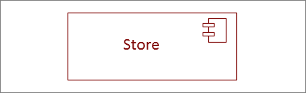
Component shapes
When to utilise
Use component shapes for each functional unit in your system or awarding.
Bear witness or hide stereotype
Correct-click the shape to bear witness or hibernate the stereotype label.

Interface shapes
When to use
-
Utilize the Provided Interface shape when you want to specify the realization of a form/interface.
-
Use the Required Interface when y'all want to specify a dependency on a class/interface.
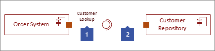
Step 1
Elevate a Provided Interface shape to the page, and line upwards the port square with a connection point. You lot know information technology'south continued when you come across the green highlight around the connection point.
Stride two
Drag a Required Interface shape to the folio, and line up the port square with a connection point equally well. You know it's connected when you encounter the light-green highlight effectually the connexion point.
Step 3
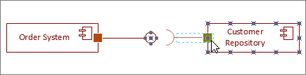
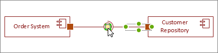
To connect both a Provided and Required interface together, starting time select the Required Interface shape. Then look for the yellow handle.
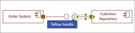
Step 4
Drag the xanthous handle to connect with the Provided Interface.
See Also
UML diagrams in Visio
Create a UML component diagram
Create a UML advice diagram
Create a UML sequence diagram
Source: https://support.microsoft.com/en-us/office/create-a-uml-deployment-diagram-ef282f3e-49a5-48f5-a6ae-69a6982a4543
0 Response to "Draw Deployment Diagram Online Free"
Post a Comment